2.1 LAN
2.1.1 Physical Layer
Various symbols are used to represent media types. Token Ring is represented by a circle. FDDI is represented by two concentric circles and the Ethernet symbol is represented by a straight line. Serial connections are represented by a lightning bolt.
 Each computer network can be built with many different media types. The function of media is to carry a flow of information through a LAN. Wireless LANs use the atmosphere, or space, as the medium. Other networking media confine network signals to a wire, cable, or fiber. Networking media are considered Layer 1, or physical layer, components of LANs.
Each type of media has advantages and disadvantages. These are based on the following factors:
- Cable length
- Cost
- Ease of installation
- Susceptibility to interference
Coaxial cable, optical fiber, and space can carry network signals. This module will focus on Category 5 UTP, which includes the Category 5e family of cables.
2.1.2 Cabling LAN’s
Ethernet is the most widely used LAN technology. Ethernet was first implemented by the Digital, Intel, and Xerox group (DIX). DIX created and implemented the first Ethernet LAN specification, which was used as the basis for the
A network may require an upgrade to one of the faster Ethernet topologies. Most Ethernet networks support speeds of 10 Mbps and 100 Mbps.
The new generation of multimedia, imaging, and database products can easily overwhelm a network that operates at traditional Ethernet speeds of 10 and 100 Mbps. Network administrators may choose to provide Gigabit Ethernet from the backbone to the end user. Installation costs for new cables and adapters can make this prohibitive.
There are several ways that Ethernet technologies can be used in a campus network:
- An Ethernet speed of 10 Mbps can be used at the user level to provide good performance. Clients or servers that require more bandwidth can use 100-Mbps Ethernet.
- Fast Ethernet is used as the link between user and network devices. It can support the combination of all traffic from each Ethernet segment.
- Fast Ethernet can be used to connect enterprise servers. This will enhance client-server performance across the campus network and help prevent bottlenecks.
- Fast Ethernet or Gigabit Ethernet should be implemented between backbone devices, based on affordability.
2.1.3 UTP Implimentations
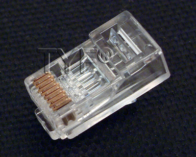
EIA/TIA specifies an RJ-45 connector for UTP cable. The letters RJ stand for registered jack and the number 45 refers to a specific wiring sequence. The RJ-45 transparent end connector shows eight colored wires. Four of the wires, T1 through T4, carry the voltage and are called tip. The other four wires, R1 through R4, are grounded and are called ring. Tip and ring are terms that originated in the early days of the telephone. Today, these terms refer to the positive and the negative wire in a pair. The wires in the first pair in a cable or a connector are designated as T1 and R1. The second pair is T2 and R2, the third is T3 and R3, and the fourth is T4 and R4.
The RJ-45 connector is the male component, which is crimped on the end of the cable. When a male connector is viewed from the front, the pin locations are numbered from 8 on the left to 1 on the right as seen in Figure:
For electricity to run between the connector and the jack, the order of the wires must follow T568A or T568B color code found in the EIA/TIA-568-B.1 standard, as shown in Figure.

To determine the EIA/TIA category of cable that should be used to connect a device, refer to the documentation for that device or look for a label on the device near the jack. If there are no labels or documentation available, use Category 5E or greater as higher categories can be used in place of lower ones. Then determine whether to use a straight-through cable or a crossover cable.
If the two RJ-45 connectors of a cable are held side by side in the same orientation, the colored wires will be seen in each.
Use straight-through cables for the following connections:
- Switch to router
- Switch to PC or server
- Hub to PC or server
Use crossover cables for the following connections:
- Switch to switch
- Switch to hub
- Hub to hub
- Router to router
- PC to PC
- Router to PC.
2.1.4 Hubs
Hubs are actually multiport repeaters. The difference between hubs and repeaters is usually the number of ports that each device provides. A typical repeater usually has two ports. A hub generally has from 4 to 24 ports.Hubs are most commonly used in Ethernet 10BASE-T or 100BASE-T networks.

The use of a hub changes the network from a linear bus with each device plugged directly into the wire to a star topology. Data that arrives over the cables to a hub port is electrically repeated on all the other ports connected to the network segment.
Hubs come in three basic types:
- Passive – A passive hub serves as a physical connection point only. It does not manipulate or view the traffic that crosses it. It does not boost or clean the signal. A passive hub is used only to share the physical media. A passive hub does not need electrical power.
- Active – An active hub must be plugged into an electrical outlet because it needs power to amplify a signal before it is sent to the other ports.
- Intelligent – Intelligent hubs are sometimes called smart hubs. They function like active hubs with microprocessor chips and diagnostic capabilities. Intelligent hubs are more expensive than active hubs. They are also more useful in troubleshooting situations.
Devices attached to a hub receive all traffic that travels through the hub. If many devices are attached to the hub, collisions are more likely to occur. A collision occurs when two or more workstations send data over the network wire at the same time. All data is corrupted when this occurs. All devices that are connected to the same network segment are members of the same collision domain.
Sometimes hubs are called concentrators since they are central connection points for Ethernet LANs.
2.1.5 Wireless Network
Wireless signals are electromagnetic waves that travel through the air. Wireless networks use radio frequency (RF), laser, infrared (IR), satellite, or microwaves to carry signals between computers without a permanent cable connection. The only permanent cabling can be to the access points for the network. Workstations within the range of the wireless network can be moved easily without the need to connect and reconnect network cables. At the core of wireless communication are devices called transmitters and receivers. The transmitter converts source data to electromagnetic waves that are sent to the receiver. The receiver then converts these electromagnetic waves back into data for the destination. For two-way communication, each device requires a transmitter and a receiver. Many networking device manufacturers build the transmitter and receiver into a single unit called a transceiver or wireless network card. All devices in a WLAN must have the correct wireless network card installed.
The two most common wireless technologies used for networking are IR and RF. IR technology has its weaknesses. Workstations and digital devices must be in the line of sight of the transmitter to work correctly. An infrared-based network can be used when all the digital devices that require network connectivity are in one room. IR networking technology can be installed quickly. However, the data signals can be weakened or obstructed by people who walk across the room or by moisture in the air. New IR technologies will be able to work out of sight.

RF technology allows devices to be in different rooms or buildings. The limited range of radio signals restricts the use of this kind of network. RF technology can be on single or multiple frequencies. A single radio frequency is subject to outside interference and geographic obstructions. It is also easily monitored by others, which makes the transmissions of data insecure. Spread spectrum uses multiple frequencies to increase the immunity to noise and to make it difficult for outsiders to intercept data transmissions.
2.1.6 Bridges
There are times when it is necessary to break up a large LAN into smaller and more easily managed segments.This decreases the amount of traffic on a single LAN and can extend the geographical area past what a single LAN can support.Switches and bridges operate at the data link layer of the OSI model. The function of the bridge is to make intelligent decisions about whether or not to pass signals on to the next segment of a network. When a bridge receives a frame on the network, the destination MAC address is looked up in the bridge table to determine whether to filter, flood, or copy the frame onto another segment. This decision process occurs as follows:
- If the destination device is on the same segment as the frame, the bridge will not send the frame onto other segments. This process is known as filtering.
- If the destination device is on a different segment, the bridge forwards the frame to the appropriate segment.
- If the destination address is unknown to the bridge, the bridge forwards the frame to all segments except the one on which it was received. This process is known as flooding.
2.1.7 Switches
A switch is sometimes described as a multiport bridge. A typical bridge may have only two ports that link two network segments. A switch can have multiple ports based on the number of network segments that need to be linked. Like bridges, switches learn information about the data frames that are received from computers on the network. Switches use this information to build tables to determine the destination of data that is sent between computers on the network

Although there are some similarities between the two, a switch is a more sophisticated device than a bridge. A bridge determines whether the frame should be forwarded to the other network segment based on the destination MAC address. A switch has many ports with many network segments connected to them. A switch chooses the port to which the destination device or workstation is connected. Ethernet switches are popular connectivity solutions because they improve network speed, bandwidth, and performance.
Switching is a technology that alleviates congestion in Ethernet LANs. Switches reduce traffic and increase bandwidth. Switches can easily replace hubs because switches work with the cable infrastructures that are already in place. This improves performance with minimal changes to a network.
All switching equipments perform two basic operations. The first operation is called switching data frames. This is the process by which a frame is received on an input medium and then transmitted to an output medium. The second is the maintenance of switching operations where switches build and maintain switching tables and search for loops.
Switches operate at much higher speeds than bridges and can support new functionality, such as virtual LANs.
An Ethernet switch has many benefits. One benefit is that it allows many users to communicate at the same time through the use of virtual circuits and dedicated network segments in a virtually collision-free environment. This maximizes the bandwidth available on the shared medium. Another benefit is that a switched LAN environment is very cost effective since the hardware and cables in place can be reused.
2.1.8 Host Connectivity
The function of a NIC is to connect a host device to the network medium. A NIC is a printed circuit board that fits into the expansion slot on the motherboard or peripheral device of a computer. The NIC is also referred to as a network adapter. On laptop or notebook computers a NIC is the size of a credit card.

NICs are considered Layer 2 devices because each NIC carries a unique code called a MAC address. This address is used to control data communication for the host on the network. More will be learned about the MAC address later. NICs control host access to the medium.
In some cases the type of connector on the NIC does not match the type of media that needs to be connected to it. A good example is a Cisco 2500 router. This router has an AUI connector. That AUI connector needs to connect to a UTP Category 5 Ethernet cable. A transceiver is used to do this. A transceiver converts one type of signal or connector to another. For example, a transceiver can connect a 15-pin AUI interface to an RJ-45 jack. It is considered a Layer 1 device because it only works with bits and not with any address information or higher-level protocols.
NICs have no standardized symbol. It is implied that, when networking devices are attached to network media, there is a NIC or NIC-like device present. A dot on a topology map represents either a NIC interface or port, which acts like a NIC.
2.2 WANs
2.2.1 Physical Layer
The physical layer implementations vary based on the distance of the equipment from each service, the speed, and the type of service. Serial connections are used to support WAN services such as dedicated leased lines that run PPP or Frame Relay. The speed of these connections ranges from 2400 bps to T1 service at 1.544 Mbps and E1 service at 2.048 Mbps.
ISDN offers dial-on-demand connections or dial backup services. An ISDN Basic Rate Interface (BRI) is composed of two 64 kbps bearer channels (B channels) for data, and one delta channel (D channel) at 16 kbps used for signaling and other link-management tasks. PPP is typically used to carry data over the B channels.
As the demand for residential broadband high-speed services has increased, DSL and cable modem connections have become more popular. Typical residential DSL service can achieve T1/E1 speeds over the telephone line. Cable services use the coaxial cable TV line. A coaxial cable line provides high-speed connectivity that matches or exceeds DSL. DSL and cable modem service will be covered in more detail in a later module.
2.2.2 Serial Connectors
For long distance communication, WANs use serial transmission. This is a process by which bits of data are sent over a single channel. This process provides reliable long distance communication and the use of a specific electromagnetic or optical frequency range.
Frequencies are measured in terms of cycles per second and expressed in Hz. Signals transmitted over voice grade telephone lines use 4 kHz. The size of the frequency range is referred to as bandwidth. In networking, bandwidth is a measure of the bits per second that are transmitted.
For a Cisco router, physical connectivity at the customer site is provided by one of two types of serial connections. The first type is a 60-pin connector. The second is a more compact ‘smart serial’ connector. The provider connector will vary depending on the type of service equipment.
If the connection is made directly to a service provider, or a device that provides signal clocking such as a channel/data service unit (CSU/DSU), the router will be a data terminal equipment (DTE) and use a DTE serial cable. Typically this is the case. However, there are occasions where the local router is required to provide the clocking rate and therefore will use a data communications equipment (DCE) cable. In the curriculum router labs one of the connected routers will need to provide the clocking function. Therefore, the connection will consist of a DCE and a DTE cable
2.2.3 Routers & Serial Connections
Routers are responsible for routing data packets from source to destination within the LAN, and for providing connectivity to the WAN. Within a LAN environment the router contains broadcasts, provides local address resolution services, such as ARP and RARP, and may segment the network using a subnetwork structure. In order to provide these services the router must be connected to the LAN and WAN.
In addition to determining the cable type, it is necessary to determine whether DTE or DCE connectors are required. The DTE is the endpoint of the user’s device on the WAN link. The DCE is typically the point where responsibility for delivering data passes into the hands of the service provider.
When connecting directly to a service provider, or to a device such as a CSU/DSU that will perform signal clocking, the router is a DTE and needs a DTE serial cable. This is typically the case for routers. However, there are cases when the router will need to be the DCE. When performing a back-to-back router scenario in a test environment, one of the routers will be a DTE and the other will be a DCE.

When cabling routers for serial connectivity, the routers will either have fixed or modular ports. The type of port being used will affect the syntax used later to configure each interface.
Interfaces on routers with fixed serial ports are labeled for port type and port number.
Interfaces on routers with modular serial ports are labeled for port type, slot, and port number. The slot is the location of the module. To configure a port on a modular card, it is necessary to specify the interface using the syntax “port type slot number/port number”. Use the label “serial 1/0”, when the interface is serial, the slot number where the module is installed is slot 1, and the port that is being referenced is port 0.
2.2.4 Routers & DSL Connections
The Cisco 827 ADSL router has one asymmetric digital subscriber line (ADSL) interface. To connect an ADSL line to the ADSL port on a router, do the following:
- Connect the phone cable to the ADSL port on the router.
- Connect the other end of the phone cable to the phone jack.

To connect a router for DSL service, use a phone cable with RJ-11 connectors. DSL works over standard telephone lines using pins 3 and 4 on a standard RJ-11 connector.
2.2.5 Setting up Console connections
To initially configure the Cisco device, a management connection must be directly connected to the device. For Cisco equipment this management attachment is called a console port. The console port allows monitoring and configuration of a Cisco hub, switch, or router.
The cable used between a terminal and a console port is a rollover cable, with RJ-45 connectors. The rollover cable, also known as a console cable, has a different pinout than the straight-through or crossover RJ-45 cables used with Ethernet or the ISDN BRI. The pinout for a rollover is as follows
:
1 to 8
2 to 7
3 to 6
4 to 5
5 to 4
6 to 3
7 to 2
8 to 1
To set up a connection between the terminal and the Cisco console port, perform two steps. First, connect the devices using a rollover cable from the router console port to the workstation serial port. An RJ-45-to-DB-9 or an RJ-45-to-DB-25 adapter may be required for the PC or terminal.Next, configure the terminal emulation application with the following common equipment (COM) port settings: 9600 bps, 8 data bits, no parity, 1 stop bit, and no flow control.

The AUX port is used to provide out-of-band management through a modem. The AUX port must be configured by way of the console port before it can be used. The AUX port also uses the settings of 9600 bps, 8 data bits, no parity, 1 stop bit, and no flow control.

1 comment:
Keep It Up Di...
Post a Comment